- Zotac g41 motherboard driver download install#
- Zotac g41 motherboard driver download driver#
- Zotac g41 motherboard driver download manual#
Zotac g41 motherboard driver download driver#
Below you can download esonic g31 motherboard audio driver for Windows.
Zotac g41 motherboard driver download install#
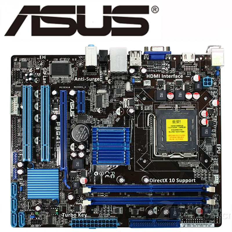
Q Chipset v Intel® G41+ICH7 q Size v Micro ATX form factor of 8.9 inch x 7.05 inch q Microprocessor support v Supports Intel® CoreTM 2 Quad/CoreTM 2 Duo/Pentium®/Celeron® Series processor v Supports Front Side Bus (FSB): 1333/1066/800 MT/s q Operating systems: v Supports Windows XP 32 bit/64 bit, Windows Vista 32 bit/64 bit and Windows 7 32bit/64bit q System Memory support v Supports dual-channel (128 bits wide) DDRIII memory interface v Supports DDRIII 1066/800 v Maximum memory size: 8 GB q USB 2.0 Ports v Supports hot plug and play v Eight USB 2.0 ports (four on the back panel, four via the USB brackets connected to the internal USB headers) v Supports USB 2.0 protocol up to 480 Mbps transmission rate q Onboard Serial ATA II v Independent DMA operation on four ports (Optional) v Data transfer rates of 3 GB/S.Download Now GSONIC G31 MOTHERBOARD DRIVERĭownload drivers for Intel R G33/G31 Express Chipset Family video cards Windows 7 圆4, or install DriverPack Solution software for automatic driver download and update Are you tired of looking for the drivers for your devices? Entrepreneurial journey with 1 To use this.

Smbios Configuration- 22 Trusted Computing- 22 USB Configuration- 22 PCI/PnP Menu- 23 Boot Menu- 24 Security Menu- 25 Chipset Menu- 26 Exit Menu- 26 Flash Update Procedure - 27 Installing Drivers and Software- 28 Drivers Installation - 29 REALTEK HD AUDIO DRIVER SETUP - 34 Getting Started- 34 Sound Effect- 34 Environment Simulation- 34 Equalizer Selection - 35 Karaoke Mode- 35 Mixer- 36 Playback control- 36 Recording control- 37 Audio I/O- 38 Speaker Configuration- 39 Connector Settings- 40 S/PDIF - 40 Speaker Calibration- 41 Microphone- 42 Noise Suppression- 42 Beam Forming- 42 Acoustic Echo Cancellation- 42 3D Audio Demo- 43 Information - 43 Motherboard Specifications- 4 Motherboard Layout- 6 Hardware Installation- 8 Safety Instructions- 8 Preparing the Motherboard- 9 Installing the CPU- 9 Installing the CPU Fan- 10 Installing Memory Modules- 10 Installing the Motherboard- 11 Installing the I/O Shield- 11 Securing the Motherboard into the chassis- 11 Connecting Cables and Setting Switches- 12 24-pin ATX Power - 13 4-pin ATX 12V Power - 13 Hard Disk Connector- 14 SPK Header- 14 SPDIF-Out Header- 14 COM Header (Optional)- 14 Front Panel Header- 15 USB Headers- 16 F_Audio Header- 16 Connecting Serial ATA Cables (Optional)- 17 Fan Connectors- 17 Expansion Slots- 18 PCIE x16 Slot- 18 PCIE x1 Slot- 18 PCI x1 Slot- 18 Jumper Settings- 19 Configuring the BIOS- 20 Enter BIOS Setup- 20 Main Menu- 20 Advanced Menu- 21 CPU Configuration- 21 IDE Configuration- 22 SuperIO Configuration -22 Hardware Health Configuration- 22 ACPI Configuration- 22 MPS Configuration- 22 PCI Express Configuration- 22 2 Trademarks All brand names, logos and registered trademarks mentioned are property of their respective owners. Neither is any liability assumed for damages resulting from the use of the information contained herein. While every precaution has been taken in the preparation of this manual, no responsibility for errors or omissions is assumed.
Zotac g41 motherboard driver download manual#
No portion of this manual may be copied or reproduced by any means. Copyright This manual is copyrighted with all rights reserved. To ensure that the use of this product does not contribute to interference, it is necessary to use shielded I/O cables. The user is cautioned that any changes or modifications not expressly approved by the party responsible for compliance could void the user’s authority to operate this equipment. NOTE: Connecting this device to peripheral devices that do not comply with Class B requirements, or using an unshielded peripheral data cable, could also result in harmful interference to radio or television reception. REORIENT OR RELOCATE THE RECEIVING ANTENNA INCREASE THE SEPARATION BETWEEN THE EQUIPMENT AND THE RECEIVER CONNECT THE EQUIPMENT INTO AN OUTLET ON A CIRCUIT DIFFERENT FROM THAT OF THE RECEIVER CONSULT THE DEALER OR AN EXPERIENCED AUDIO/TELEVISION TECHNICIAN If this equipment does cause harmful interference to radio or television reception, which can be determined by turning the equipment off and on, the user is encouraged to try to correct the interference by one or more of the following measures:.

However, there is no guarantee that interference will not occur in a particular installation. This equipment generates, uses and can radiate radio frequency energy and, if not installed and used in accordance with instructions contained in this manual, may cause harmful interference to radio and television communications. These limits are designed to provide reasonable protection against harmful interference in a residential installation. Federal Communications Commission (FCC) Statement This equipment has been tested and found to comply with the limits for a Class B digital device, pursuant to Part 15 of FCC Rules.


 0 kommentar(er)
